Hi Michael,
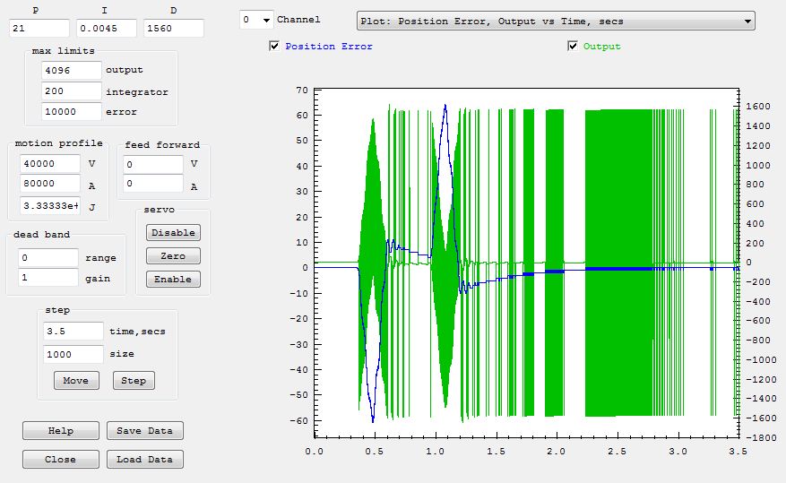
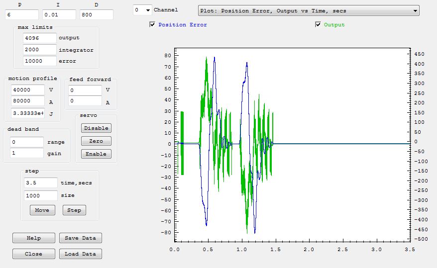
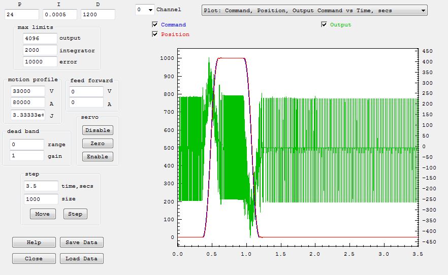
The D Gain of 1650 is set way too high. Notice the huge spikes in the Output (Green) of 1650 counts? The full range of the output is +/- 2047 DAC counts so this is nearly a full output spike. This is because a minimum change of 1 encoder count/sample x 1650 adds 1650 DAC counts to the output. The DAC and Amplifier will do nonlinear things with those huge swings.
Reduce the D Gain and add a low pass filter (like 2nd order 1000Hz Q=1.4). You will likely have to reduce the P and I gains to have a stable system.
The redo the tuning of increasing P I D gains to see how it goes.
Regards
TK
| Group: DynoMotion |
Message: 4219 |
From: Michael Rosenfield |
Date: 3/13/2012 |
| Subject: Re: velocity servo tuning |
Thanks! I'll try that in the morning. Michael
| Group: DynoMotion |
Message: 4220 |
From: Michael Rosenfield |
Date: 3/14/2012 |
| Subject: Re: velocity servo tuning |
Tom, I did that, and things changed, but I can't see that there is much improvement in following error. What is the Bode plot telling me? The time domain plot looks kind of strange. Regards, Michael
| Group: DynoMotion |
Message: 4221 |
From: Tom Kerekes |
Date: 3/14/2012 |
| Subject: Re: velocity servo tuning [4 Attachments] |
Hi Michael,
That is better but the system appears to have a lot of friction, low bandwidth, and be very sluggish. You aren't providing much of any information on what sequence you have performed and what the results were.
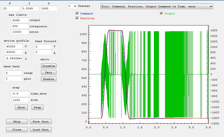
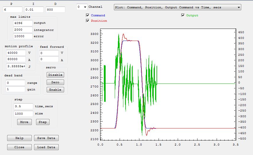
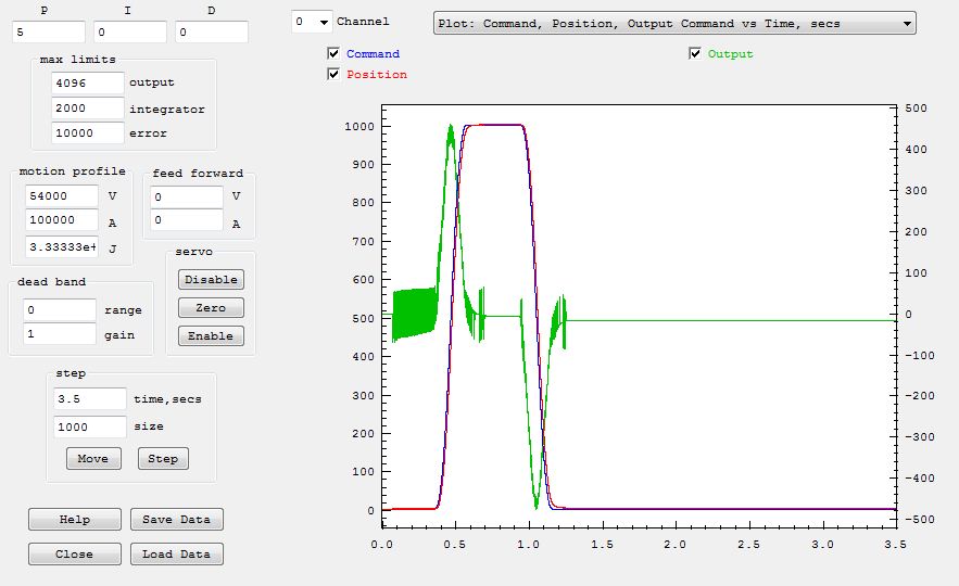
If you were to zoom in (left mouse click drag) on the first plot right where it starts to move you could probably see this clearly. The trajectory (blue plot) starts to move causing an error which causes the output (green plot) to increase but the encoder position (red plot) remains still for quite a while before it breaks free and even begins to move.
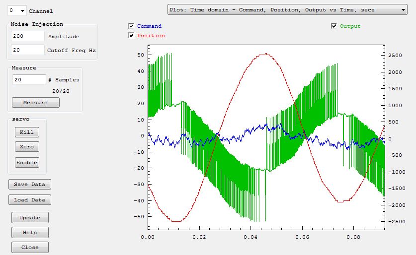
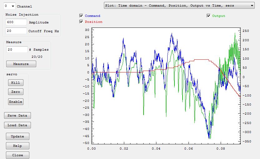
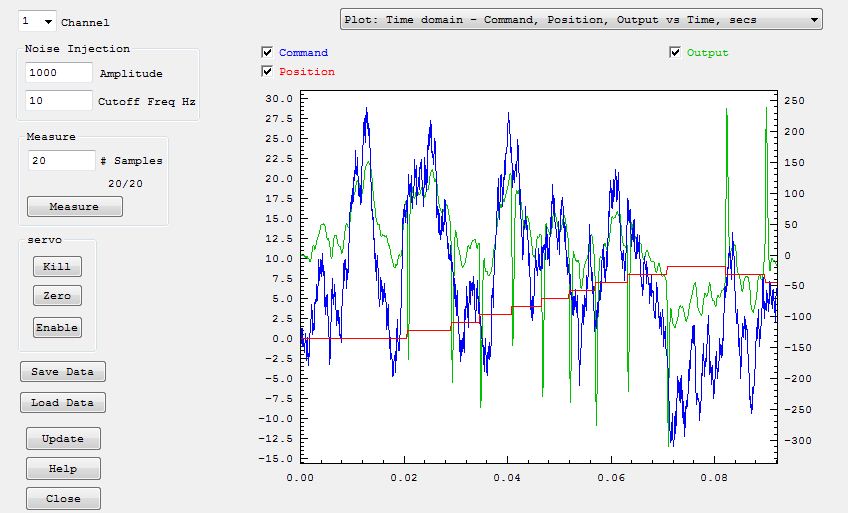
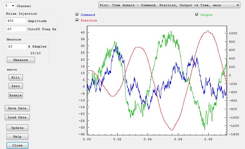
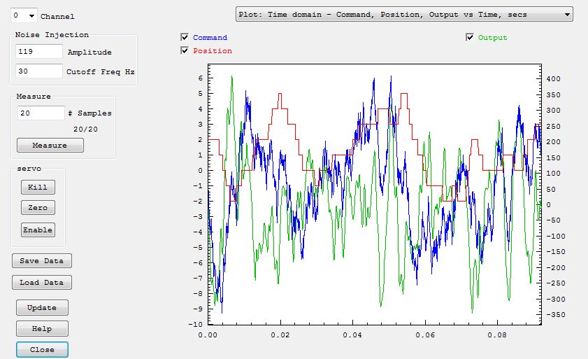
The same thing can be shown in the Bode Plot Time domain data. Looking towards the beginning the random blue plot is the commanded trajectory. This causes the somewhat random output (green plot), but the position (red plot) doesn't move at all.
The output goes above 100 DAC counts (which is ~ 5% of full speed) with no motor movement at all.
You might be able to overcome this by cranking up the gains but it doesn't seem right.
Either the mechanics has lots of friction or binding, or possibly the amplifier isn't configured and tuned properly.
You might go back to testing the amplifier. If you command 50 or 100 DAC counts does the motor move? Does it move at a tightly controlled speed?
Also the Integrator I gain seems quite high. Zero it out and tune P D first for the best performance. The I term is normally used for correcting small but persistent errors but it looks like it is being used for the bulk of the output.
HTH
TK
| Group: DynoMotion |
Message: 4222 |
From: Michael Rosenfield |
Date: 3/14/2012 |
| Subject: Re: velocity servo tuning |
As far as testing the amp - when the system gets a following error, the KFlop shuts the axis down, but outputs about 20mV on the analog output in quesiton. This causes the axis to move slowly but consistently and smoothly. According to my calculations, this is 4 counts. This happens on either axis. So I'd have to say that 4 counts makes each of the 2 axes move. The machine is a knee mill, with 5:1 ballscrews. It is heavy, but moves smoothly by hand. The encoders are 1000 CPR USDigital with differential outputs, attached by toothed belt to the ballscrew drive pulley. The motor pulley is about 1/5 the diameter of the ballscrew pulley (toothed belt, again). The amps are set to velocity mode, where 10V=2500 rpm at the motor. This translates to about 500 rpm at the encoder. I'm going to verify the amp settings again. I started with a gain of .5, and started increasing P, D, and I while watching the error plot, and backing things down when I get oscillation. I guess I really don't know what I'm doing... I can set the amps for current mode instead of velocity mode - would this be better? The motors already had tachs on them, so I just figured I'd use them. Does this information help? Michael
| Group: DynoMotion |
Message: 4223 |
From: Tom Kerekes |
Date: 3/14/2012 |
| Subject: Re: velocity servo tuning |
Hi Michael,
Yes that was useful. Sounds like it is more like slow amplifier response causing the delay to move rather than just friction.
It is probably better to stick with the velocity mode and tach feedback if the amplifier can be made to do tight velocity control. There are two reasons for this: it probably provides more accurate velocity than the limited resolution encoder can and it detects velocity at the motor rather than after the belt. Please check the settings again as you said. There is probably a tach feedback gain pot on the amplifier. Try increasing that. You basically want to increase it until it starts to go unstable then back it off a bit.
After that if we could get a useful Bode plot it would help understand things. The previous Bode plots were pretty useless as there was hardly any movement correlated to the command. If the amplifier tach feedback is turned up, the PD gains increased a bit, and larger Bode plot stimulus we may be able to get useful measurements.
Hang in there :}
TK
| Group: DynoMotion |
Message: 4224 |
From: Michael Rosenfield |
Date: 3/14/2012 |
| Subject: Re: velocity servo tuning |
Ok, I brought up the gain on the amp, and verified that 10v=2500 rpm, and 0=0.
Also found a bit of slack in the encoder belt.
Now what do you make of these plots? I don't see much change in the frequency domain, even though the position appears to move.
Regards,
Michael
| Group: DynoMotion |
Message: 4225 |
From: Michael Rosenfield |
Date: 3/14/2012 |
| Subject: Re: velocity servo tuning |
Tom,
Here is the x axis. The motion is following the output, but out of phase. What does that mean?
Otherwise, it has low following error - 45 counts max. Lot of noise on the output, though.
Michael
| Group: DynoMotion |
Message: 4226 |
From: Tom Kerekes |
Date: 3/15/2012 |
| Subject: Re: velocity servo tuning [3 Attachments] |
Hi Michael,
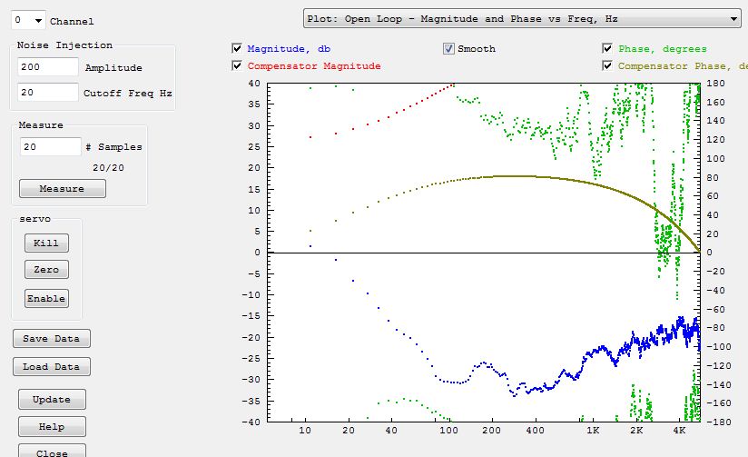
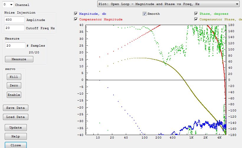
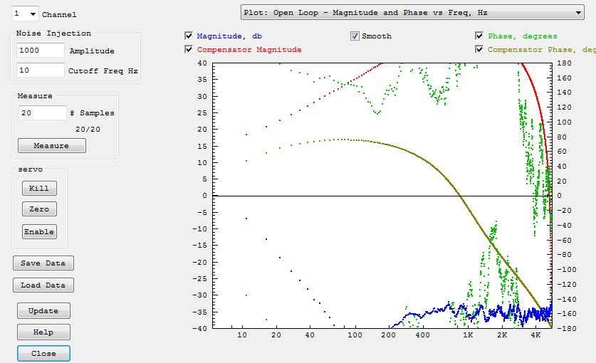
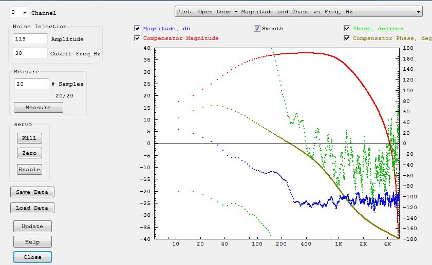
Those are a little better. I still don't understand what is going on with the system. Normally the position feedback loop around a velocity servo is pretty easy and stable with simple P gain and no D gain at all (what happens when you try that?). But in your case you are putting a huge amount of D gain and still have less phase margin than normal. I'm not sure if I can fully trust the Bode plot because there still isn't much correlated motion, but it is showing very little phase margin at the 0db crossover at ~30Hz. The huge D gain should be providing lots of +phase so that doesn't make sense to me. Is it correct that you have belt between the motor and the leadscrew, and then another belt between the lead screw and the encoder?? These may be the cause of the phase lag.
We can try to add additional +phase at 30 Hz with a lead lag compensator. Set filter #1 to Pole-Zero mode, set N1,N2 to 15HZ and D1,D2 to 60Hz. You may need to decrease other gains to get a stable system.
(I think the sort of out-of phase stuff is normal. That is basically saying that when we are too far ahead to drive backwards).
Regards
TK
| Group: DynoMotion |
Message: 4227 |
From: Michael Rosenfield |
Date: 3/15/2012 |
| Subject: Re: velocity servo tuning |
The y axis has motor belt to leadscrew, and then another belt from leadscrew to encoder. The x axis has belt from motor to leadscrew, and the encoder is mounted to the leadscrew. When I have P and no D, I get a significant delay between command and motion, although it is accurate eventually. As I add P to decrease the following error, I have to add D to keep it stable. I did add a lead lag compensator, with just those values. I didn't reduce the gain, however, so I got oscillation. I'll go back later and try it again with lowered gain. The axes act quite differently, which I didn't quite expect. So the question is - what am I actually trying to accomplish? I assumed I want to tune things so the step input produces a following error less than 20 counts, which is 0.001" So far, I am running around 17 on each axis. I can email more screen captures, if that would help. Thanks again, Michael
| Group: DynoMotion |
Message: 4228 |
From: Tom Kerekes |
Date: 3/15/2012 |
| Subject: Re: velocity servo tuning |
Hi Michael,
You actually want to do a "Move" rather than a "Step" (which is probably what you meant).
The goal is to get the accuracies at the speeds and accelerations that you need.
Regards
TK
| Group: DynoMotion |
Message: 4229 |
From: Michael Rosenfield |
Date: 3/15/2012 |
| Subject: Re: velocity servo tuning |
I noticed that responses change between 1000 counts, 4000 counts, and 10,000 counts. Is this normal?
| Group: DynoMotion |
Message: 4230 |
From: Tom Kerekes |
Date: 3/15/2012 |
| Subject: Re: velocity servo tuning |
Don't know what you mean?
| Group: DynoMotion |
Message: 4231 |
From: Michael Rosenfield |
Date: 3/15/2012 |
| Subject: Re: velocity servo tuning |
If I tune for no oscillation with a 1000 count move, and then do a 4000 count move, it may or may not oscillate. I got the 4000 count move working, and tried a 10,000 count move, and the following error was so great it shut the axis down. Is this expected?
| Group: DynoMotion |
Message: 4232 |
From: Tom Kerekes |
Date: 3/15/2012 |
| Subject: Re: velocity servo tuning |
No that isn't normal. I would need to see a plot. But the bigger move might be getting up to a higher velocity or higher acceleration that exceeds some limit. The plot will tell the whole story.
| Group: DynoMotion |
Message: 4233 |
From: Michael Rosenfield |
Date: 3/15/2012 |
| Subject: Re: velocity servo tuning |
Tom,
Here are the results of putting the lead lag comp in place, and lowering the gain.
What does this tell you?
Looks like I need to get a book on servo theory!
BTW, this is on the x axis, so the encoder is direct drive on the ballscrew.
Regards,
Michael
| Group: DynoMotion |
Message: 4234 |
From: Tom Kerekes |
Date: 3/15/2012 |
| Subject: Re: velocity servo tuning [4 Attachments] |
Hi Michael,
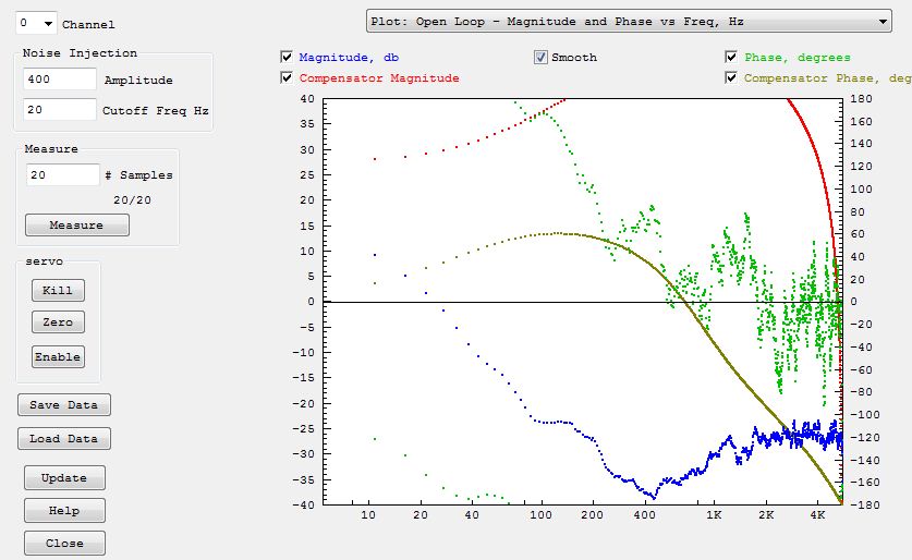
That is looking better. Notice the phase margin is much higher.
In the Bode plot time domain you can see that the encoder is only moving a few counts so there isn't much information being obtained and the encoder resolution becomes an issue making good measurements. Lower the frequency of the stimulus and increase the Amplitude to get more accurate measurements.
We could probably shoot for higher servo bandwidth. Increase the P gain. Theoreticaly this shifts the entire magnitude plot (blue) upward which in turn will shift the 0db crossover point to the right. Changing P gain should have no effect on the phase plot (green). We can probably shoot for 60 Hz or higher. At the same time shift the Lead/Lag compensator to the right so it is geometrically centered on the crossover point because we want the max phase margin at that point.
Then add in a bit of I gain.
Regards
TK
| Group: DynoMotion |
Message: 4235 |
From: Michael Rosenfield |
Date: 3/15/2012 |
| Subject: Re: velocity servo tuning |
I'll try this in the morning. Why is my Bode plot not listing the gain and phase margins as shown in the documentation? Thanks for all your help, Tom! Michael
| Group: DynoMotion |
Message: 4236 |
From: Tom Kerekes |
Date: 3/15/2012 |
| Subject: Re: velocity servo tuning |
Hi Michael,
The data is probably too noisy and too low of bandwidth for it to find the crossover. You might turn off "smoothing" to see how the raw data is. It is better to use your eye anyway. There are a lot of issues with Bode Plot measurements because of encoder not being infinitely precise, disturbances, mechanical/electrical non linearities, etc... that result in noise in the measurements. So you should be suspicious in what it shows. But it can still provide invaluable clues to what is going on that would be very difficult to see in the time domain.
Regards
TK
| Group: DynoMotion |
Message: 4237 |
From: Michael Rosenfield |
Date: 3/15/2012 |
| Subject: Re: velocity servo tuning |
When I turn off the smoothing, the phase looks like a fog of random dots - I couldnt see any pattern to it at all. The magnitude was not too much different, if I recall correctly.
| Group: DynoMotion |
Message: 4240 |
From: Tom Kerekes |
Date: 3/16/2012 |
| Subject: Re: velocity servo tuning |
That was my point
| Group: DynoMotion |
Message: 4241 |
From: mrosenfield@hotmail.com |
Date: 3/16/2012 |
| Subject: Re: velocity servo tuning |
Tom,
The raw data matches the smootned data pretty well below 800 hz or so.
The lead lag moved the phase margin. The magnitude hasn't changed much, even with increased p gain.
Problem is, now the output is oscillating at a few hundred hz, but the position is stable. What do I do about this? Sometimes it quits, sometimes not.
Regards,
Michael
Sent from my Verizon Wireless Phone -----Original message----- From: Tom Kerekes <tk@...>
To: "DynoMotion@yahoogroups.com" <DynoMotion@yahoogroups.com>
Sent: Fri, Mar 16, 2012 02:07:34 GMT+00:00
Subject: Re: [DynoMotion] velocity servo tuning
Hi Michael,
The data is probably too noisy and too low of bandwidth for it to find the crossover. You might turn off "smoothing" to see how the raw data is. It is better to use your eye anyway. There are a lot of issues with Bode Plot measurements because of encoder not being infinitely precise, disturbances, mechanical/electrical non linearities, etc... that result in noise in the measurements. So you should be suspicious in what it shows. But it can still provide invaluable clues to what is going on that would be very difficult to see in the time domain.
Regards
TK
| Group: DynoMotion |
Message: 4242 |
From: Tom Kerekes |
Date: 3/16/2012 |
| Subject: Re: velocity servo tuning |
Hi Michael,
You aren't being very decriptive on what you changed and how the results changed.
The oscillation is probably 1 count servo dither. If you set the "Move" size to zero you can probably plot what is going on. Did you add I gain? This is usually what causes servo dither. A tiny error gets integrated and causes the output to ramp up to overcome friction to make a correction. When it finally moves it is likely to overshoot - especially in your case where you have belts between the motor and the encoder. The tachometer feedback with high gain is the most effective way to detect motion at the motor. This is usually so small it doesn't hurt anything but is annoying. Deadband is often successful at eliminating it. It can be used to basically ignore (deadband gain of zero) small errors (deadband range) or correct them less aggressively (ie. deadband gain of 0.1).
Regards
TK
| Group: DynoMotion |
Message: 4243 |
From: Michael Rosenfield |
Date: 3/16/2012 |
| Subject: Re: velocity servo tuning |
| |
| | | | | | | | | | | | | | | | | | | | | | | | | | | | | | | | | | | | | | | | | | | |